|
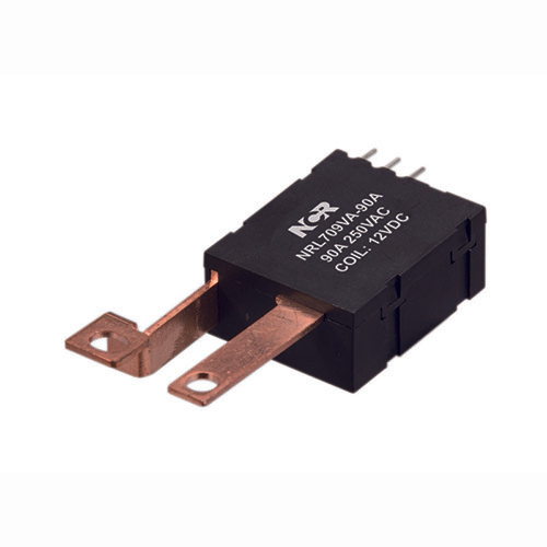
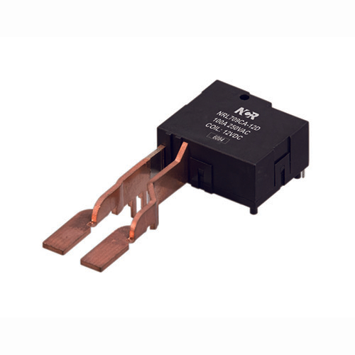
◆ Ordering Information
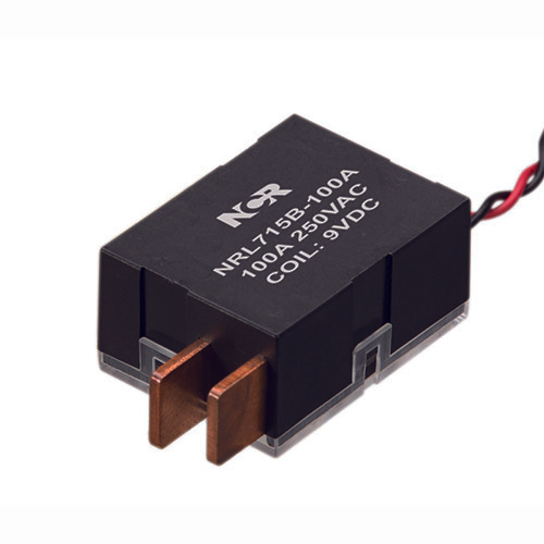
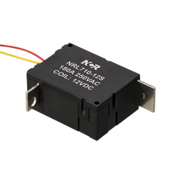
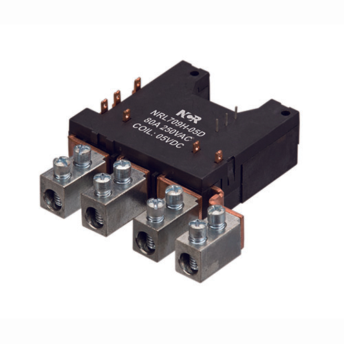
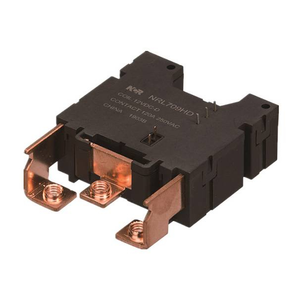
 | ① Latching Relay |
② Part Number | |
③ Coil Voltage | |
④ D= Double Coil; S= Single Coil | |
⑤ 100=100A |
◆ Characteristics
Insulation resistance | 1000MΩ (500VDC) | ||
Dielectric Strength | Between Coil & Contacts | 4000VAC 1min | |
Between Open Contacts | 2000VAC 1min | ||
Pole&Pole | 4000VAC 1min | ||
Operate Time | 20msec. Max. | ||
Release Time | 20msec. Max. | ||
Shock resistance | Functional | 98m/S2 | |
Destructive | 980m/S2 | ||
Vibration resistance | 10~55Hz 1.5mm | ||
Humidity | 5%-85%RH | ||
Ambient temperature | -40~+85℃ | ||
Temination | Fast connection | ||
Unit weight | 90g | ||
Constrution | Dust protected | ||
◆ Contact Data
Contact form | 2A/2B |
Contact material | AgSnO2 |
| Contact resistance (1A 6VDC) (Test point within 5mm distance from the casing ) | Max: 0.8mΩ |
Contact Rating | 100A 250VAC |
Max. Switching Current | 100A |
Max. Switching Voltage | 277VAC |
Max. Switching Power | 25000VA |
Mechanical life | 1×10 5 |
Electrical life ( Resistive) | 1×10 4 |
◆ Coil
Coil power | Single coil: 4.0W Double coil: 8.0W |
◆ Coil Data
Rated Voltage | (VDC) Pick-up voltage | Pulse Duration | Coil Resistance | |
Single coil | ||||
9 | ≤ 6.8 | ≥ 50 | 20±10% | |
12 | ≤ 9 | ≥ 50 | 36±10% | |
| 24 | ≤ 18 | ≥ 50 | 144±10% | |
| 48 | ≤ 36 | ≥ 50 | 576±10% | |
Double coil | ||||
9 | ≤ 6.8 | ≥ 50 | 2×110±10% | |
12 | ≤ 9 | ≥ 50 | 2×18±10% | |
| 24 | ≤ 18 | ≥ 50 | 2×72±10% | |
| 48 | ≤ 36 | ≥ 50 | 2×288±10% | |
Note: Special ordering for other coil voltage.
◆ Typical Application
1)Prepayment Energy Meter; AMR System;
2)Compound Switch; Automatic Control System.
ELECTRICAL ENDURANCE
| UC Class | Voltage (Uc) | Current (Ic) | Power Factor | Close Open time (s) | Electricalenduran ce(ops) | |
| UC3 | 220VAC | 80A | COSφ=1 | 10:20 | 5000 | Total 10000 |
| COSφ=0.5 | 5000 | |||||
Notes: 1) Electrical endurance meet lEC62052-31 test requirement,do the inductive load test after the resistive load test。
2) The line is driven by rated voltage
◆Dimensions(mm)/Circuit Diagram