Views: 0 Author: Site Editor Publish Time: 2026-03-19 Origin: Site
A Current Transformer (CT) is a fundamental electromagnetic instrument utilized to scale primary electrical currents from high-voltage distribution lines into standardized, manageable secondary currents. This conversion enables safe measurement and real-time monitoring through conventional instrumentation and protective logic. The primary technical objective of a CT is to facilitate galvanic isolation, thereby decoupling high-potential power systems from low-potential sensing circuitry. As global energy utilities move toward Advanced Metering Infrastructure (AMI), the requirement for precision sensing components from NCR Industrial has become a benchmark for system integrity.
In the context of modern smart grid requirements, a Current Transformer must perform with linear accuracy across a dynamic range, ensuring that secondary signals are exact replicas of primary waveforms. This guide analyzes the operational physics, material engineering, and selection criteria required for integrating CTs into state-of-the-art smart metering and industrial protection systems.
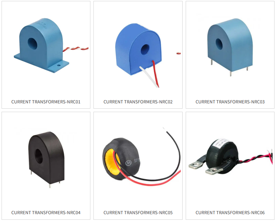
Current transformers manufactured by NCR are engineered to withstand the rigorous environmental and electrical stresses of utility-scale energy monitoring. Technical performance is defined by the following industrial characteristics:
Utility Energy Meter Sensing: Optimized for use as primary sensing devices in revenue-grade billing systems.
Environmental Resilience: Engineered to be moisture-proof and vibration-resistant for deployment in varied geographic climates.
Dielectric Integrity: Encapsulation by epoxy resin ensures high insulation capacity, mitigating the risk of inter-winding breakdown.
Flame Retardancy: Casings are constructed from flame-retardant PBT (Polybutylene Terephthalate), meeting safety requirements for high-density electrical panels.
Standard Compliance: DC-tolerance versions are available, strictly adhering to the IEC 62053-21 international standard for static meters for active energy.
A Smart Meter is a state-of-the-art diagnostic device designed to record electricity consumption in real-time or near real-time. To ensure billing accuracy and grid stability, NCR provides an integrated component ecosystem. The synergy between sensing and execution components defines the reliability of the AMI network.
| Integrated Component | Technical Role in Smart Metering | NCR Material/Process Standard |
|---|---|---|
| Current Transformer (CT) | Scaling and isolation of primary current for MCU analysis. | Nanocrystalline/Silicon Steel cores; PBT casing. |
| Latching Relay | Remote load switching and fault isolation. | Magnetic latching mechanism; high-current busbars. |
| Shunt | Local current sensing with high linearity. | Manganin alloy; Electron Beam Welding (EBW). |
| Brass Terminal & Cage Clamp | Mechanical and electrical interface stability. | High-conductivity brass alloys. |
| Super Capacitor | Backup power for "Last Gasp" data transmission during outages. | High energy density; long cycle life. |
The operational logic of a current transformer is predicated on the laws of electromagnetic induction. The primary conductor, typically a cable or busbar carrying the load current, acts as a single-turn primary winding. The primary current (I1) generates a variable magnetic field within the high-permeability core. This flux induces a secondary current (I2) in the secondary winding, which is inversely proportional to the turns ratio of the transformer.
For revenue-grade metering, the secondary output current is standardized between 0 and 5 amps (or 0 to 1 amp for long-distance transmission). This standardization allows for the integration of universal meters and protective relays, regardless of the system's primary current magnitude.
Accuracy Class and long-term stability are direct functions of material selection. NCR employs Epoxy Resin Encapsulation to protect the magnetic core and copper windings from atmospheric oxidation and moisture ingress, which can otherwise alter the core's permeability and increase Phase Angle Error. The use of flame-retardant PBT for the casing ensures thermal stability during overcurrent events, preventing the risk of internal combustion within the distribution board.
Selecting the correct NCR Current Transformer requires a rigorous analysis of the electrical and physical environment. Two primary technical criteria must be evaluated:
The rated current of the CT must be matched to the rating or setting of the directly upstream circuit breaker. To maintain operation within the linear region of the magnetic core, the CT rating should equal or slightly exceed the breaker setting. For instance, if an industrial circuit breaker is set to 95 amperes, the next highest standardized CT rating (100A) is the appropriate selection. This prevents Magnetic Saturation during peak load periods.
Mechanical compatibility is as critical as electrical specification. Installation requirements vary depending on the conductor type:
Cable Installation: Evaluation must be based on the external diameter of the cable (including insulation and jacketing) to ensure the CT aperture can accommodate the conductor without mechanical stress.
Busbar Installation: It is mandatory to verify both the height and width dimensions of the busbar. NCR provides both solid-core and split-core configurations to facilitate installation in existing busbar architectures without disconnecting the circuit.
The Rated Burden is the maximum impedance (in Volt-Amps, VA) that the CT secondary circuit can support while maintaining its designated Accuracy Class. This burden includes the combined resistance of the secondary leads and the internal impedance of the connected meter. If the total burden exceeds the CT's capacity, the output current will become non-linear. For compact designs where space is highly limited, engineers may opt for a board-mounted EBW Manganin Shunt to provide local current sensing, though this technology does not provide the inherent safety of galvanic isolation.
Modern electrical loads often introduce DC components into AC power lines. Standard current transformers may saturate in the presence of DC, leading to significant billing errors. NCR offers specialized DC-tolerance current transformers that utilize advanced core materials (such as nanocrystalline alloys) to remain accurate in the presence of DC offsets, ensuring compliance with IEC 62053-21 for high-precision energy measurement.
The most critical safety protocol in Instrument Transformer engineering is the prevention of a secondary open circuit. If the secondary terminals are opened while the primary is energized, the counter-magnetizing force disappears, causing the core flux to rise rapidly. This generates a high-voltage spike across the secondary terminals—potentially exceeding several kilovolts—resulting in dielectric failure, arcing, and lethal risk to personnel. All CT secondaries must remain connected to a load or short-circuited during primary operation.
Magnetic saturation is characterized by "waveform clipping," where secondary current fails to track primary peaks. Symptoms of saturation include erratic power factor readings and energy under-reporting. NCR engineers recommend verifying the Accuracy Limit Factor (ALF) of the CT during the design phase to ensure fault currents are accurately reflected in protection logic.
The integration of current transformers into power systems is a technical process governed by principles of electromagnetism and material science. By utilizing NCR precision components, including CTs, Latching Relays, and Shunts, engineers can establish a reliable and accurate smart metering framework. Compliance with IEC 62053-21 and the appropriate calculation of rated burdens and physical dimensions ensure long-term grid stability and billing integrity. For comprehensive technical datasheets and selection support, consult the NCR Industrial engineering documentation.
The Accuracy Class (e.g., 0.5s or 0.2s) is determined by the magnetic core's permeability and the precision of the secondary winding turns. It defines the maximum permissible ratio error at standardized load points.
Epoxy resin provides high dielectric strength and environmental sealing, protecting the internal components from moisture-induced corrosion and mechanical vibration, which is critical for outdoor utility meters.
Standard CTs are AC induction devices. However, NCR produces specific DC-tolerance versions designed to maintain accuracy even when AC lines carry DC components, as required by the IEC 62053-21 standard.
The ratio is determined by dividing the peak primary current (based on upstream breaker rating) by the standardized secondary output (typically 5A). A 200A system would utilize a 200:5 ratio CT.